X/Y (coincident)
Two cardioids with capsules on top of each other, angled 90–135°. Level differences only, so it collapses to mono perfectly. Solid and focused, a little narrow. Great for drum overheads and acoustic guitar.
A microphone does not simply “hear.” It measures pressure and pressure gradients from particular directions. Move a performer and monitor wedge around four pickup patterns, trace a wireless transmitter-to-receiver link, compare five classic stereo miking geometries, and use the 3:1 rule to prevent multi-mic comb filtering.
A polar pattern is a directional behavior—not a body style. Two microphones can look alike and respond very differently, and some studio microphones can switch patterns. These are real, representative examples; confirm any microphone’s pattern from its label or specification sheet.
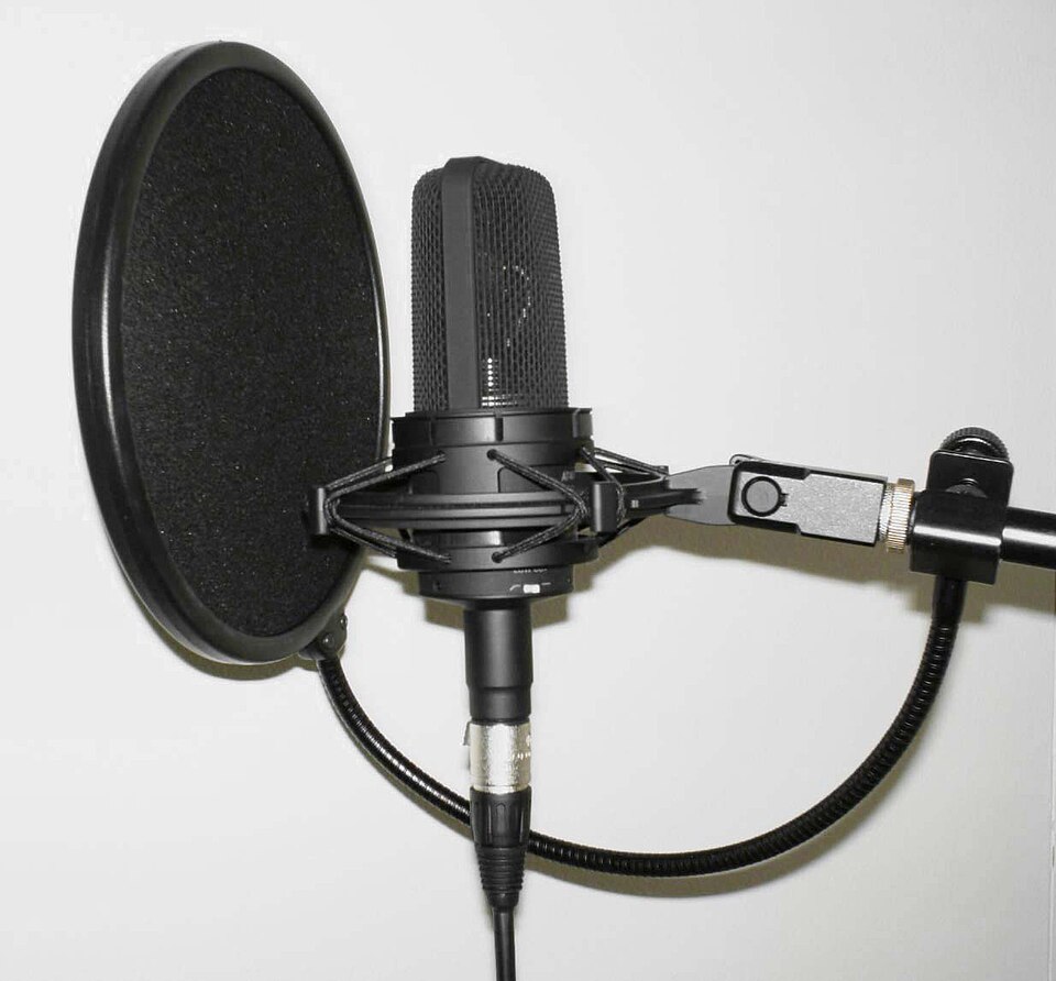
Side-address condenser: many fixed-pattern studio condensers use cardioid pickup. Speak toward the marked front—not into the top—and always verify the pattern on the mic or spec sheet.
Author-released public domain · Wikimedia Commons ↗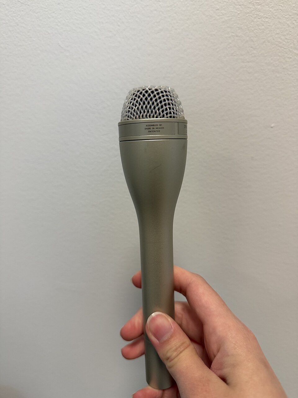
Shure SM61: an omni responds to pressure at one side of its diaphragm. It has no intentional rear null and does not exhibit directional proximity effect.
CC0 public-domain dedication · Wikimedia Commons ↗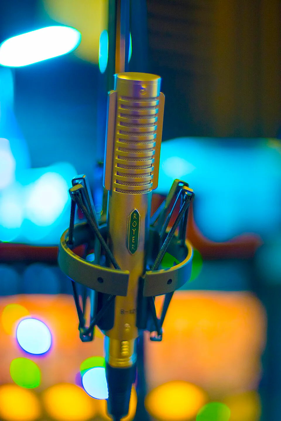
Royer R-121: sound reaches both faces of its ribbon. Front and rear are sensitive with opposite polarity, while equal side pressure produces deep 90° nulls.
CC0 public-domain dedication · Wikimedia Commons ↗
Boom-mounted shotgun: slots along its long tube delay off-axis sound so portions cancel before reaching the capsule. Directionality varies with frequency.
U.S. State Department public domain · Wikimedia Commons ↗Wireless does not remove the signal chain—it replaces one cable with a radio link. The microphone still creates an audio signal, the transmitter sends it by radio frequency (RF), and the receiver converts it back to audio for the mixer. Next: how to coordinate up to eight of them →
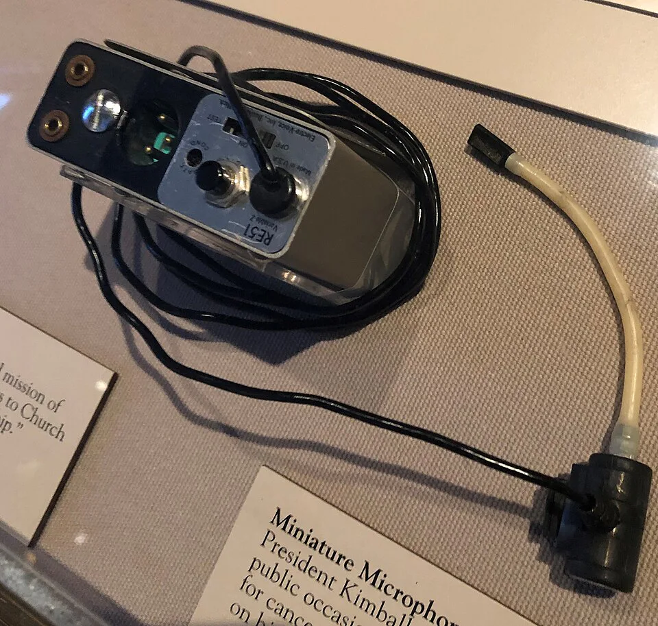
The capsule stays a consistent distance from the mouth while the bodypack supplies power, accepts the mic signal, and transmits it on an assigned RF channel.
CC0 public-domain dedication · Wikimedia Commons ↗
Each receiver listens for its paired transmitter, displays RF and audio status, then sends audio through XLR or ¼-inch output to one mixer channel.
CC0 public-domain dedication · Wikimedia Commons ↗A stereo pair uses two microphones so the recording keeps where each instrument was: left, centre or right. Your ears locate sound two ways: by level differences (louder in one ear) and by time differences (arrives at one ear first). Each stereo technique uses one or both.
Two cardioids with capsules on top of each other, angled 90–135°. Level differences only, so it collapses to mono perfectly. Solid and focused, a little narrow. Great for drum overheads and acoustic guitar.
Two cardioids 17 cm apart (about ear-width), angled 110°. Level and small time differences: wider and more natural than X/Y, still mostly mono-safe. A favourite for choirs and pianos.
Two (usually omni) mics a few feet apart. Mostly time differences: big, airy, roomy. Easy to get a "hole in the middle" if too far apart, and the least mono-safe. Check it in mono.
Two figure-8s, coincident, at 90°. The front lobes capture the ensemble, the rear lobes capture the room behind you. Gorgeous in a good-sounding room, unforgiving in a bad one.
A cardioid "mid" faces the source; a figure-8 "side" faces left-right. Decode: Left = M + S, Right = M − S. Turn S up or down after recording to change the width. Perfect mono: just the mid mic.
The rule: when two mics are open on different sources, each source's neighbouring mic must be at least three times as far away as its own mic. Singer 30 cm from her mic? The guitar mic stays at least 90 cm from her.
The why: the singer also leaks into the guitar mic, a little later and a little quieter. Mix both mics and you have two copies of her voice, slightly out of time. Some frequencies line up and add; others arrive opposite and cancel. That's comb filtering, and it makes voices sound thin, hollow and phasey. The inverse-square law says that at 3× the distance the leak is about 9.5 dB quieter, which shrinks the comb's notches to about 3.5 dB, small enough that you stop hearing them. Drag the distances and see:
The same comb filtering is why stereo pairs need care, why you check polarity between a snare top and bottom mic, and why a mic near a reflective music stand or table can sound hollow: the reflection is a second, late copy.