🎚 Analog Mixer Lab: Patch, Gain & FX Bus
Set up a 12-channel analog mixer the way a real audio tech does: pick the right cable for every microphone, instrument, and speaker, then work real rotary knobs and vertical faders to trace the signal from preamp to fader, and route AUX sends into a reverb/delay FX bus.
Channel numbering, jack types, and control layout mirror a real 12-channel console (like the TASCAM Model 12) so the hand motions transfer. The chassis artwork, colors, and code here are an original simulation — not the manufacturer's software.1 · Patch Bay — Wire the Stage
Channel 1's condenser mic needs +48V phantom power to work. Dynamic mics and instruments never need it — leaving it on for them is harmless but pointless.
0 / 5 connections correct
2 · Signal Flow — Click Every Stage
↳ AUX sends tap off here → Monitor bus & FX bus
Pick a stage Click any block above to see what it does to the signal on its way from the stage to the speakers.
3 · Channel Strips — drag the knobs and faders like the real console
Input channels 1–12 · scroll to see the whole console
4 · Master Section & FX Bus
✨ FX Bus — Reverb / Delay
Pre-fader vs. post-fader sends AUX 1 (Monitor) is tapped pre-fader — right after the preamp — so a performer's stage monitor mix doesn't jump around when you ride their channel fader. AUX 2 (FX) is tapped post-fader, so the reverb tail rises and falls together with the dry vocal, the way it should.
Why a shared FX bus? Instead of giving every channel its own reverb, the console sends a little of each channel to one shared reverb via AUX 2, then blends that single wet signal back in with the FX Return knob on the master strip. Start the return low — it's easy to add more, hard to un-hear too much.
📊 Meters
CLIP
Ch.1
-∞
Monitor
-∞
FX Bus
-∞
CLIP
Master
-∞
Patch the mics correctly and bring up gain to see healthy meters.
📷 Meet the real gear
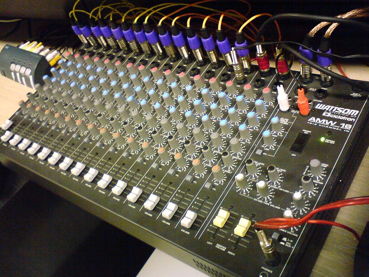
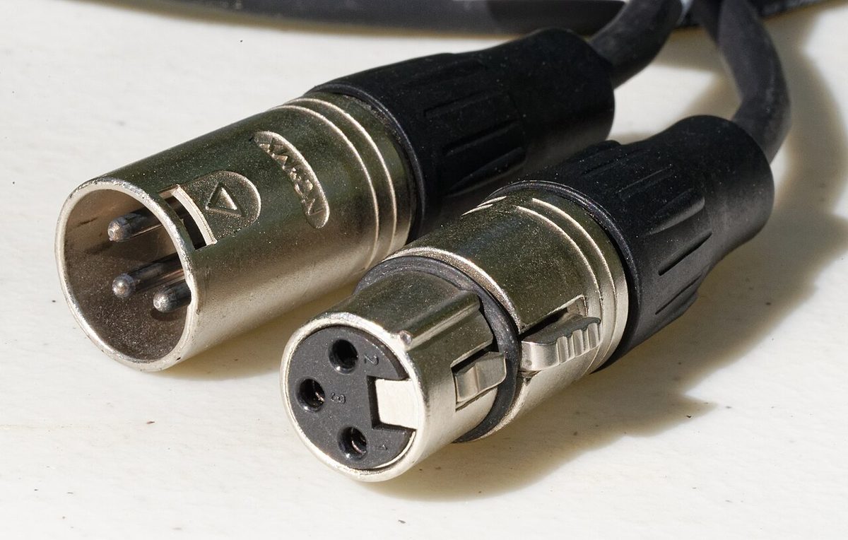
The mixer in the lab is drawn to match real consoles like these. Find the gain knob, the EQ section and the fader on the first photo, then click any photo to enlarge it.