Plan, elevation, section
Separate measured views showed where an opening sat and how its frame met the wall.
Start with the editable technique workshop above. Reuse your model in the next lesson. The detailed walkthrough below uses Blender; choose another app using Tool Rosetta and the transfer checklist above.
Hard-Surface Modeling · 70–90 minutes · Grades 7–12
Build a reusable two-meter wall panel with a centered window. Use a live Boolean to cut the opening, assemble measured frame pieces, and fit four panes. Keep this module for the room you will build in Lesson 04.
Finish line: a 2m × 2m wall panel, a 1.2m-square opening, and a named collection you can reuse.
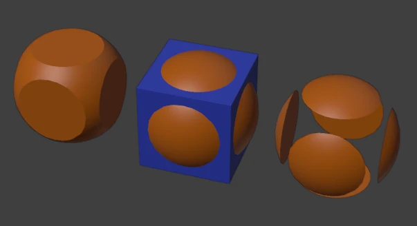
From measured drawing to editable opening
A doorway or window begins as a measured relationship: opening, frame, structure, and repeated parts. Drafting made those relationships visible on paper; CAD made them revisable; modern solid and polygon tools let one volume cut another while the design remains editable.
Separate measured views showed where an opening sat and how its frame met the wall.
Interactive drawing systems made copies and dimensions easier to change without redrawing the whole sheet.
A cutter volume can subtract an opening, while modifiers preserve the steps for later revision.
Predict: Why is keeping the cutter more like keeping a construction drawing than carving a permanent hole by hand?
History source: Computer History Museum: Sketchpad and direct manipulation
02-window-module.blend with a collection named WindowModule. Lesson 04 will append this entire collection, including the cutter.Plan
One coordinate system for the whole pathway
X is width, Y is thickness, Z is height. The floor is Z = 0. The wall is centered at X = 0, Y = 0; its center is one meter above the floor. This is a classroom model module, not a building-code specification.
Dimensions X = 2m, Y = 0.15m, Z = 2m. Location (0, 0, 1). Its bottom is 1 − 2 ÷ 2 = 0m.
A 1.2m × 1.2m opening centered at (0, 0, 1). The wall left around it is (2 − 1.2) ÷ 2 = 0.4m on every side.
Dimensions (1.2, 0.45, 1.2)m. Its 0.45m depth extends 0.15m past each wall face, so the cut goes completely through.
DO · Save any current project first. Choose File → New → General. With the pointer over the 3D Viewport in Object Mode, press A, then X and confirm Delete to remove the new default objects. In the Outliner, double-click the remaining Collection name and rename it WindowModule; keep it as the active collection.
Open Properties → Scene → Units: set Unit System to Metric, Unit Scale to 1.000, and Length to Meters. In the viewport, use Shift+S → Cursor to World Origin. Use View → Viewpoint → Front (or Numpad 1) to look along the wall's thickness axis.
CHECK · You have an empty scene, the WindowModule collection, and a front view with X horizontal and Z vertical.
REPAIR · If shortcuts act on the Outliner, move the pointer back over the viewport. If the mode selector says Edit Mode, press Tab to return to Object Mode before adding separate objects.
In Object Mode: Add → Mesh → Cube, press F2 to name it, then open N → Item. Enter the stated Dimensions X/Y/Z and Location X/Y/Z; leave Rotation at 0°. Press Enter after each field. Then, with the pointer over the viewport, use Ctrl+A → Scale. Scale should become 1, 1, 1 while dimensions stay the same. This makes later bevel sizes predictable. Manual: Apply transforms.
Boolean
Make the wall, then remove a volume
LOOK · The wall and cutter share the same center. Only the cutter is deeper than the wall.
DO · In Object Mode, use the cube recipe to create WallPanel: Dimensions (2, 0.15, 2)m, Location (0, 0, 1)m. Add a second cube named WindowCut: Dimensions (1.2, 0.45, 1.2)m, Location (0, 0, 1)m. Apply Scale on each.
With WindowCut selected, set Object Properties → Viewport Display → Display As → Wire. This makes its outline visible without covering the wall; it does not hide it from renders.
CHECK · Front view shows a centered square inside the wall. Orbit using the middle mouse button, or drag the navigation gizmo, and check that the cutter sticks out on both sides.
REPAIR · If both cubes became one mesh, undo back before the second cube, make sure you are in Object Mode, and add it again. You need two separate Outliner rows for a Boolean operand.
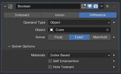
WindowCut, not the example's Cube. Official Blender Manual screenshot · CC BY-SA 4.0.DO · Select WallPanel in the Outliner. Open Properties → Modifiers (wrench) → Add Modifier → Generate → Boolean; if needed, search the Add Modifier menu for Boolean. Choose Difference, Operand Type Object, Object WindowCut, and Solver Exact. Leave the modifier in the stack.
Select WindowCut and press H with the pointer over the viewport to hide it locally. In Outliner → Filter (funnel) → Restriction Toggles, enable the camera column. Turn off the camera toggle on the WindowCut row so the cutter is also hidden from final renders. Leave the WindowModule collection enabled. The eye/H toggle and camera toggle do different jobs.
CHECK · Orbit the wall: see through the opening and see thickness on its four inside edges. The Boolean remains on WallPanel; WindowCut remains in the Outliner with its eye closed and rendering disabled.
REPAIR · If the wall is still solid, check the modifier is on WallPanel, its Object field is WindowCut, and its viewport display icon is enabled. If the whole wall vanished, check you chose Difference instead of Intersect and restore the cutter dimensions.
Your WallPanel and WindowCut at the lesson’s exact sizes, with Blender’s Boolean modifier panel and Outliner toggles. Rehearse steps 2–3 here, then use the repair bench to practise the Fix list below.
Step 1
Each button loads a broken copy of the finished module. Diagnose it, fix it, and the cause appears here.
View: drag to orbit, right-drag to pan, scroll to zoom, click an object to select it (Shift+click adds). Keys in the view: H hides the selection, Alt+H reveals all, X or Delete deletes, Ctrl+Z undoes, F12 toggles the render preview. Location and Dimensions accept typed values, like Blender’s Sidebar. The cut is computed exactly, so every size in the Result line is real.
This browser can’t show 3D graphics (WebGL is off), so the Boolean lab is unavailable. Do steps 2–3 in Blender instead.
Use File → Save As and save 02-window-module.blend. A live modifier needs its cutter: do not delete WindowCut. To adjust it later, reopen its Outliner eye, select it, change a dimension or position, then hide it again. Manual: Boolean modifier · Manual: eye and camera toggles.
Frame
A frame assembled from measured parts
LOOK · Each rail is 0.08m wide and 0.20m deep. The frame surrounds the opening and projects 0.025m beyond each wall face. The longer side rails cover the ends of the shorter top and bottom rails: simple butt joints.
In Object Mode, use the cube recipe: Dimensions (0.08, 0.20, 1.36)m, Location (−0.64, 0, 1)m. Apply Scale.
With FrameLeft selected in Object Mode, press Shift+D, then Esc to cancel only the movement. The duplicate still exists. Rename it FrameRight, and change Location X to 0.64m.
Add a new cube: Dimensions (1.20, 0.20, 0.08)m, Location (0, 0, 0.36)m. Apply Scale.
Duplicate FrameBottom with Shift+D, then Esc. Rename it FrameTop, and change Location Z to 1.64m.
CHECK · Front view shows a complete frame around a still-empty 1.2m-square opening. Its outside spans X = −0.68 to +0.68 and Z = 0.32 to 1.68. There are four named rail objects.
REPAIR · If a corner has a gap, compare Location and Dimensions separately. Locations describe centers: 0.64 = half the opening (0.60) + half the rail (0.04). If one rail flickers, look for an extra duplicate left at the original location.
Build
Divide, fit, and finish
LOOK · A vertical bar and two shorter horizontal bars divide the opening into four squares. Each clear square is (1.20 − 0.04) ÷ 2 = 0.58m wide and high.
DO · In Object Mode, add MuntinVertical using the cube recipe: Dimensions (0.04, 0.08, 1.20)m, Location (0, 0, 1)m. Add MuntinLeft: Dimensions (0.58, 0.08, 0.04)m, Location (−0.31, 0, 1)m. Apply Scale on both. Duplicate MuntinLeft, cancel the movement, rename it MuntinRight, and set Location X = 0.31m.
CHECK · You have four equally sized spaces. The short bars meet the sides of the vertical bar, and all three bars sit inside the frame's depth.
REPAIR · If one bar runs through the wall, check the axis order: Y is its 0.08m depth, not its length. Keep all object rotations at 0° for this build.
DO · In Object Mode, add a cube named PaneLowerLeft: Dimensions (0.576, 0.012, 0.576)m, Location (−0.31, 0, 0.69)m. Apply Scale. This is a thin solid pane, with 0.002m clearance per edge. Duplicate it one at a time with Shift+D, Esc; rename each and enter its full Location:
(0.31, 0, 0.69)m
(−0.31, 0, 1.31)m
(0.31, 0, 1.31)m
CHECK · Four separate pane objects share the same dimensions. In Solid shading they look opaque: this is expected. Lesson 07 handles materials; a mesh name does not make an object transparent.
REPAIR · To inspect the cut again, hide only the four pane objects using their Outliner eyes. Reopen those eyes after checking. Avoid Alt+H here: it also reveals the cutter.
LOOK · A bevel creates a narrow surface that can catch a highlight along an edge.
DO · Select FrameLeft. Open Properties → Modifiers → Add Modifier → Generate → Bevel. Set Affect to Edges, Width Type to Offset, Amount to 0.003m, Segments to 2, and Limit Method to Angle (30°). Keep Clamp Overlap on. Repeat these settings on the other three frame rails and the three muntin bars. Leave the wall, cutter, and panes as they are.
CHECK · Zoom in and orbit: the frame edges have a small chamfer, and the four openings remain recognizable. Each of those seven parts has Scale 1, 1, 1 and one Bevel modifier.
REPAIR · If bevels look uneven, apply that object's Scale. If too much material disappears, confirm the amount is 0.003m (3mm), not 0.3m. Keep flat shading while inspecting these simple solids. Manual: Bevel controls.
Press Ctrl+S. Expand WindowModule: it should contain 13 objects — one wall, one hidden cutter, four frame rails, three bars, and four panes. Keep them separate and keep the Boolean live. Lesson 04 uses File → Append → 02-window-module.blend → Collection → WindowModule.
Fix
Recover before rebuilding
Every Boolean problem below has a broken file waiting in the Boolean lab’s repair bench. Practise the diagnosis there before you need it on your own wall.
The wall still depends on its cutter. Move the complete module, including WindowCut, or use the collection workflow in Lesson 04. If you duplicate a wall, inspect its Boolean Object field before editing: a wall-only copy can still refer to the original cutter.
H and the eye toggle affect the viewport. Disable WindowCut's camera toggle in the Outliner too. Do not turn off the Boolean modifier's render icon: that removes the cut from the rendered wall.
Check that WindowCut is a closed cube, depth 0.45m, centered at Y = 0. Restore these values and use Exact. Applying Scale helps measurement-dependent modifiers; it cannot fix a cutter that misses the wall or a mesh with missing faces.
First check for duplicate objects or overlapping faces causing Z-fighting. If you suspect reversed normals or bad topology, select the affected closed mesh, enter Edit Mode, press A, then Shift+N to recalculate outside; return to Object Mode. Merging by distance (M) can also clean up bad topology.
Adding a modifier leaves it editable. Apply writes its result into the mesh and removes that modifier. For this lesson keep the live version. If a later export needs a permanent cut, first use File → Save As to make 02-window-baked-copy.blend. In Object Mode select WallPanel, open the Boolean modifier header's dropdown, and choose Apply. Verify the opening remains, then delete WindowCut only in that copy. Keep the original module file for revisions. Applying object Scale and applying a modifier are different operations. Manual: modifier stack and Apply.
Save As 02-door-study.blend. In this copy, delete the four rails, three bars, and four panes, leaving the wall and cutter. Reveal WindowCut; set Dimensions to (0.9, 0.45, 1.82)m and Location to (0, 0, 0.9)m, then Apply Scale. Its bottom now reaches Z = −0.01, just below the wall base, and its top reaches Z = 1.81. Hide the cutter again and keep its camera disabled. Check that the doorway is open at floor level, rather than leaving a thin threshold. Explain why an ordinary window cutter placed above the floor would fail this test. Keep 02-window-module.blend unchanged for the room lesson.
Check
Show the model and explain your choices
Definition of done