A breadboard only becomes useful once you can recognize the parts going into it. This module gives you a practical field guide to the foundational components students most often confuse: resistors, LEDs, capacitors, diodes, transistors, and buttons. Sensor boards such as photoresistor modules live in the separate sensor modules kit lesson.
When you pick up an unknown part, ask four questions in order: What family is it?Does polarity matter?What markings or shape give away its value?How should it sit on a breadboard? That simple checklist prevents most beginner mistakes.
1. Identify the body Cylinder, bead, disk, button, and three-legged package shapes each hint at a different component family.
2. Check polarity LEDs, electrolytic capacitors, and diodes must face the correct direction. Resistors and most ceramic capacitors do not.
3. Read the marking Color bands, printed numbers, flat sides, and longer leads all communicate value or orientation.
4. Place with intention Spread leads across separate rows so the component bridges nodes instead of shorting itself into one strip.
Resistor Color Code Guide
This upgraded analyzer blends our classroom lesson with the best ideas from a modern resistor-band simulator. You can now decode 4-band, 5-band, and 6-band resistors, compare beginner parts with precision parts, and watch the decoded meaning update live.
Schematic SymbolA resistor is drawn as a zig-zag in many classroom diagrams. Its job is to oppose current flow.
Most classroom resistors are 4-band parts.
220 Ωdigits 22 × 10tolerance ±5%
Decoded BandsRed • Red • Brown • Gold
Precision NoteStandard classroom resistor
Band Meanings In 4-band mode the first two bands are digits. In 5-band and 6-band mode the first three bands are digits. The last band is tolerance, and the 6th band adds temperature coefficient in ppm per degree C.
Orientation Tip The tolerance band is usually spaced a little farther from the other bands. Hold that band on the right while reading from left to right.
Colors
Value
Typical Use
Red, Red, Brown, Gold
220 Ω ±5%
Common LED current-limiting resistor
Brown, Black, Red, Gold
1 kΩ ±5%
Pull-up and pull-down circuits
Yellow, Violet, Orange, Gold
47 kΩ ±5%
Sensor voltage dividers
Brown, Black, Green, Gold
1 MΩ ±5%
High-resistance input circuits
Component Field Guide
These are the parts students meet first on a breadboard. Each one has a recognizable shape and a few orientation rules worth memorizing.
Light Emitting Diode
LED
Schematic SymbolDiode symbol plus outward arrows. The vertical bar marks the cathode side.
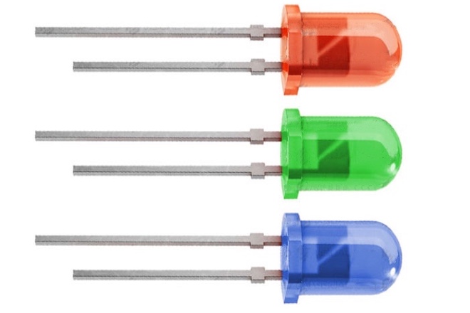
An LED allows current to flow in one direction and glows when current passes through it. It is a diode designed to emit light.
How to spot it: clear or colored plastic bulb with two leads.
Polarity: longer lead is usually the anode (+), shorter lead and flat edge mark the cathode (-).
Breadboard tip: place each leg in a different row and always use a resistor in series.
Common mistake: reversing the LED or connecting it without a resistor.
Polarized Capacitor
Electrolytic Capacitor
Schematic SymbolPolarized capacitor: one plate is marked positive, and the curved plate is often the negative side.
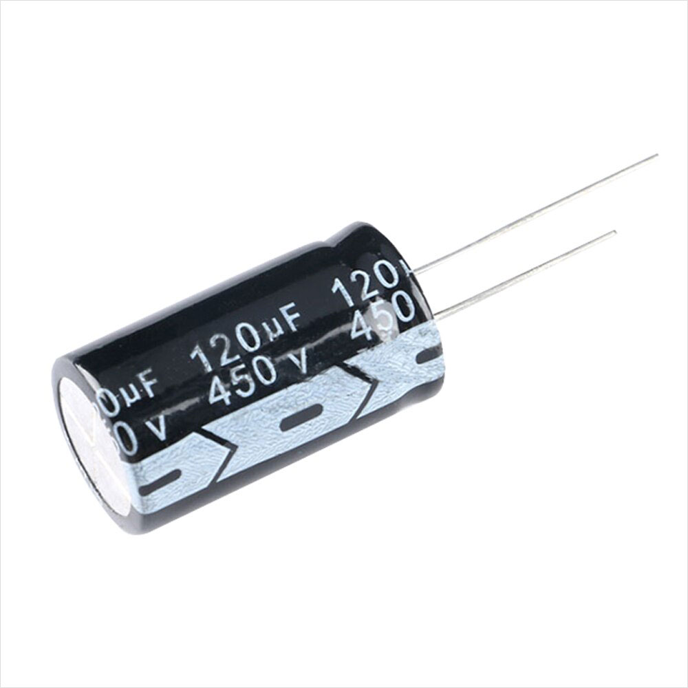
An electrolytic capacitor stores charge and is useful when you need larger capacitance values for smoothing or timing.
How to spot it: cylindrical can with printed stripe.
Polarity: the stripe marks the negative side; the longer lead is often positive.
Breadboard tip: double-check polarity before powering the circuit.
Common mistake: inserting it backwards, which can damage the part.
Non-Polarized Capacitor
Ceramic Capacitor
Schematic SymbolTwo equal plates mean non-polarized. Either lead can face either direction.
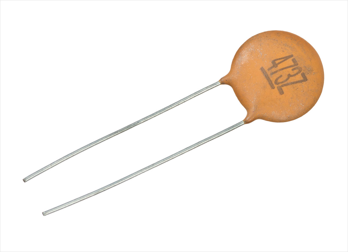
Ceramic capacitors store small amounts of charge and are often used for filtering noise and stabilizing voltage.
How to spot it: small disk, bead, or tiny rectangular package.
Polarity: none, so either lead can go in either direction.
Marking: printed codes like 104 often mean 100,000 pF = 0.1 uF.
Common mistake: assuming the printed code is in microfarads without converting.
One-Way Current
Diode
Schematic SymbolThe triangle points toward the cathode bar, matching the banded side on many physical diodes.
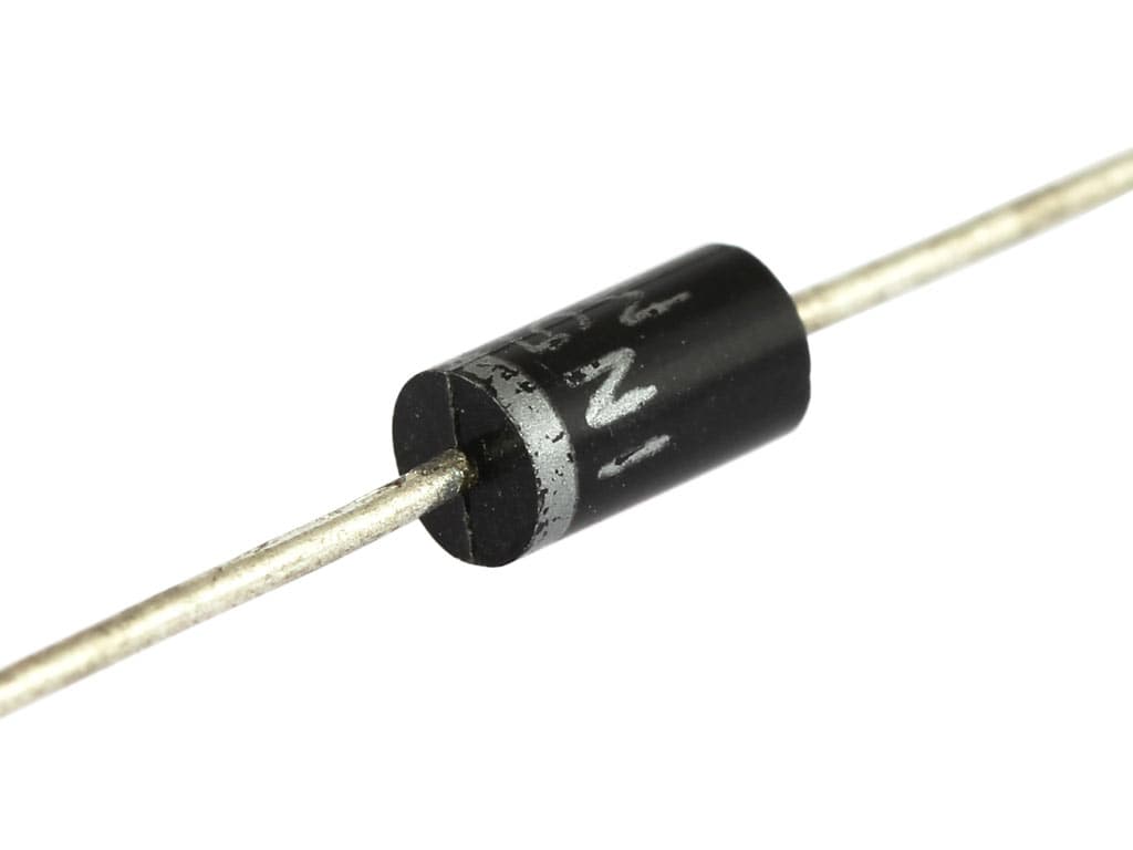
A regular diode acts like a one-way valve for current. It is used for rectification, polarity protection, and signal steering.
How to spot it: small cylinder or glass body with a band near one end.
Polarity: the band marks the cathode.
Breadboard tip: think of the band as the side current exits toward in simple diagrams.
Common mistake: mixing up the band direction and blocking current by accident.
Electronic Switch
Transistor
Schematic SymbolNPN transistor shown here: base, collector, and emitter. The emitter arrow points out.
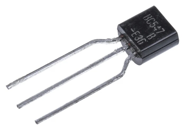
A transistor uses a small signal to control a larger current. It can work as a switch or as an amplifier.
How to spot it: usually a black half-cylinder package with three legs.
Pins: collector, base, emitter or source, gate, drain depending on transistor type.
Breadboard tip: look up the exact pinout for the part number before wiring it.
Common mistake: assuming all three-legged packages share the same pin arrangement.
Momentary Input
Button
Schematic SymbolNormally open pushbutton: the circuit is open until pressing closes the gap.
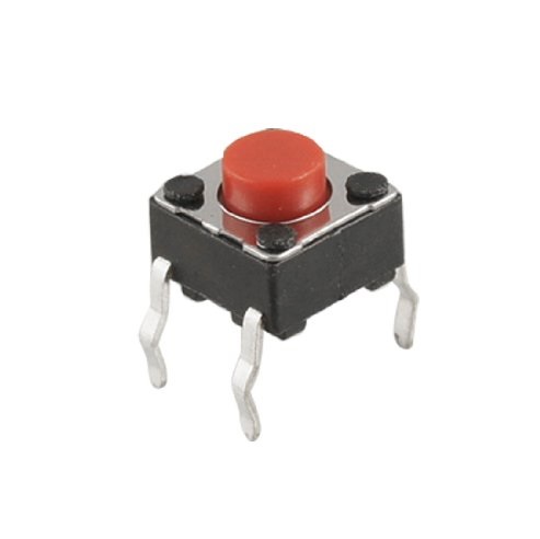
A pushbutton opens or closes a connection only while it is being pressed, making it a simple manual input device.
How to spot it: small square tactile switch with four legs.
Internal behavior: two legs on each side are already paired; pressing joins the two sides together.
Breadboard tip: straddle the center gap so the switch bridges two separate halves.
Common mistake: placing all four legs in connected rows so the button appears permanently on.
Sensor handoff: Photoresistor boards, ultrasonic boards, PIR boards, and other ready-made sensor boards are handled in the Sensor Modules Kit lesson. This page stays focused on loose foundational components.
Polarity and Placement Bench
Reading a part is only half the job. Use this bench to rehearse the physical clue that tells you which way the component belongs on a breadboard.
LED: longer lead goes toward positiveThe short lead and flat edge mark the cathode. Put a resistor in series so the LED does not pull too much current.
Ceramic Capacitor Code Decoder
Many tiny capacitors use a three-digit code. The first two digits are the value, and the third digit tells how many zeros to add in picofarads.
Decoded Value100 nF
104 means 10 followed by 4 zeros: 100,000 pF.
103 means 10,000 pF, which is 10 nF.
221 means 220 pF.
Compare the Parts
Use this table when sorting parts from a mixed electronics kit.
Component
Main Job
Polarity?
What to Notice First
Resistor
Limits current or sets voltage ratios
No
Color bands around a small cylinder
LED
Emits light when current flows
Yes
Long and short legs, flat edge
Electrolytic Capacitor
Stores larger charge, smooths voltage
Yes
Cylindrical can, negative stripe
Ceramic Capacitor
Filters noise, bypasses signals
No
Small disk or bead with a number code
Diode
Allows one-way current flow
Yes
Band marking the cathode end
Transistor
Switches or amplifies current
Pin order matters
Three-legged package and part number
Button
Temporary user input
No, but orientation affects pairing
Four legs in two internal pairs
Common Troubleshooting Checks
When a circuit refuses to work, the problem is often not the idea but the orientation of one small part.
LED is dark Check polarity first, then confirm the resistor is in series instead of accidentally bypassed.
Capacitor heats up Power off immediately and check whether an electrolytic capacitor is reversed.
Button always reads pressed The switch is probably rotated the wrong way or sitting in one connected breadboard strip.
Transistor does nothing Verify the part number and exact pinout; the flat face alone is not enough to guarantee pin order.
Current will not pass Check diode orientation. A single reversed diode can block the whole branch.
Quick Check
1. On a four-band resistor, what do the first two color bands represent?
2. What marking most clearly identifies the negative side of an electrolytic capacitor?
3. Why does the band on a diode matter?
4. Why should a four-leg tactile button usually straddle the breadboard center gap?