A sensor kit turns a microcontroller from a simple board into a device that can react to light, sound, motion, heat, touch, distance, and time. This lesson organizes a common beginner sensor modules kit into useful categories, highlights the most important safety notes, and helps students decide which module to try first.
Use these original concept diagrams as quick visual anchors while students sort the kit by what each board senses.
33 Examples
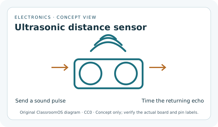
Pin WiringVCC to 5VGND to GNDTRIG to digital outputECHO to digital input
Ultrasonic sensor module for distance measurement. Original ClassroomOS concept diagram · CC0 1.0; verify the actual component and pin labels.
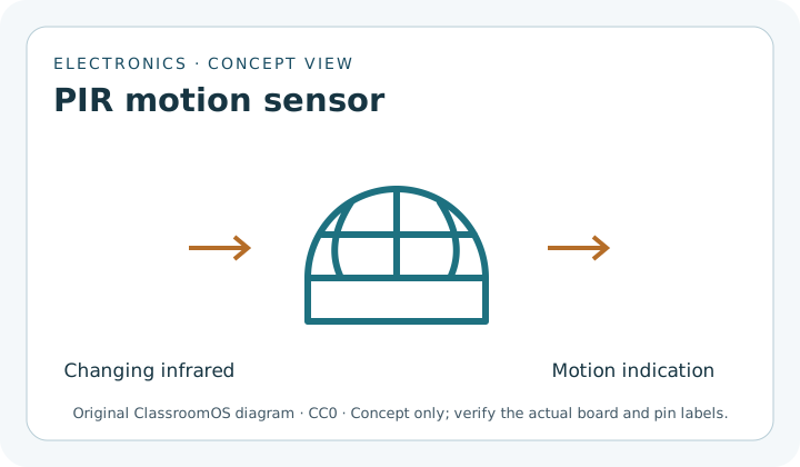
Pin WiringVCC to 5VGND to GNDOUT to digital input
PIR sensor module for detecting motion. Original ClassroomOS concept diagram · CC0 1.0; verify the actual component and pin labels.
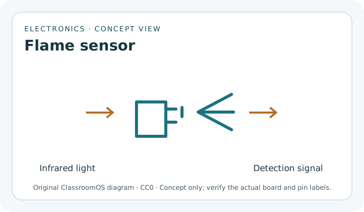
Pin WiringVCC to 5VGND to GNDDO to digital inputAO to analog input
Flame sensor module for detecting infrared light from fire. Original ClassroomOS concept diagram · CC0 1.0; verify the actual component and pin labels.
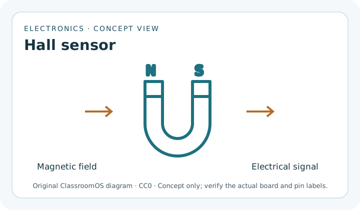
Pin WiringVCC to 5VGND to GNDAO to analog inputDO to digital input
Linear Hall module for sensing magnetic fields. Original ClassroomOS concept diagram · CC0 1.0; verify the actual component and pin labels.
Pin WiringVCC to 5VGND to GNDS to digital input
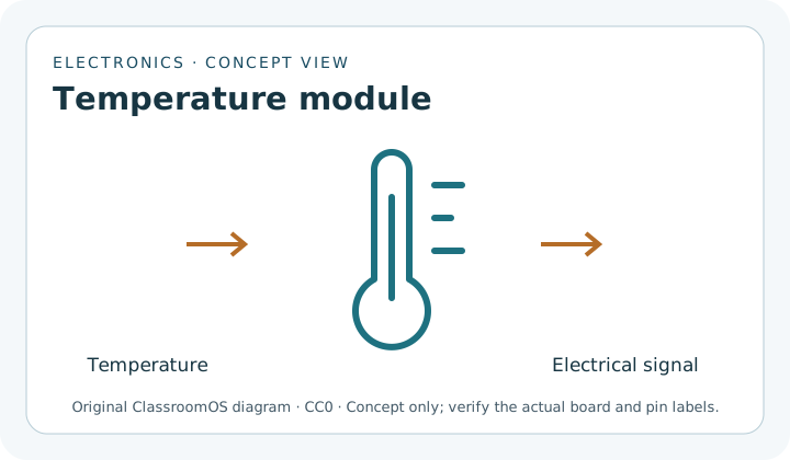
Digital temperature module for sensing heat. Original ClassroomOS concept diagram · CC0 1.0; verify the actual component and pin labels.
Pin WiringVCC to 5V or 3.3VGND to GNDDQ/S to digital data pin
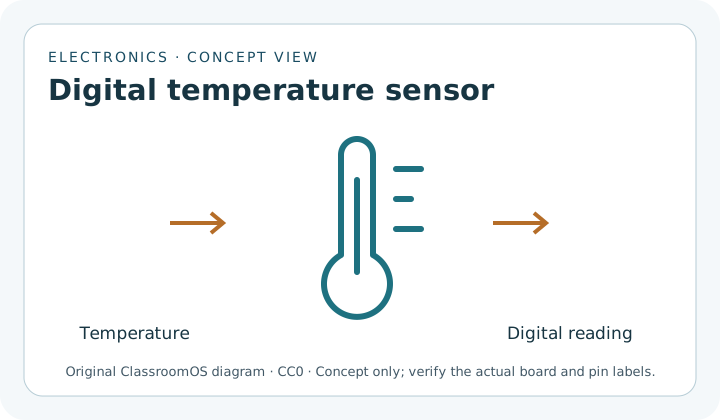
18B20 module for digital temperature readings. Original ClassroomOS concept diagram · CC0 1.0; verify the actual component and pin labels.
Pin WiringVCC to 5V or 3.3VGND to GNDDATA/S to digital input
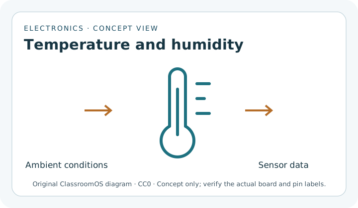
Temperature and humidity module for measuring air conditions. Original ClassroomOS concept diagram · CC0 1.0; verify the actual component and pin labels.
Pin WiringVCC to 5VGND to GNDAO to analog inputDO to digital input
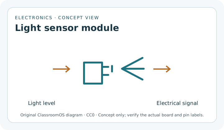
Photoresistor module for measuring light level. Original ClassroomOS concept diagram · CC0 1.0; verify the actual component and pin labels.
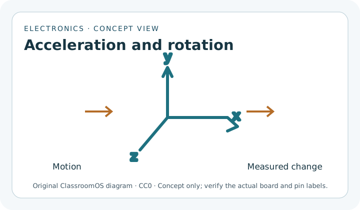
Pin WiringVCC to 3.3V or 5VGND to GNDSCL to I2C clockSDA to I2C data
GY-521 motion module for acceleration and rotation. Original ClassroomOS concept diagram · CC0 1.0; verify the actual component and pin labels.
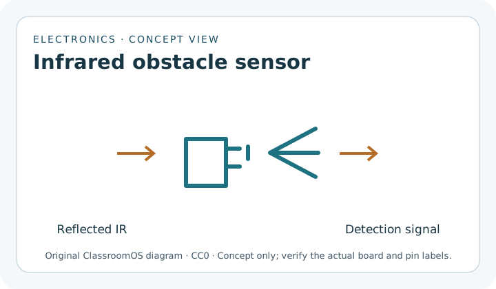
Pin WiringVCC to 5VGND to GNDOUT to digital input
Avoidance module for detecting nearby obstacles. Original ClassroomOS concept diagram · CC0 1.0; verify the actual component and pin labels.
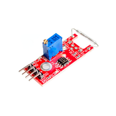
Pin WiringVCC to 5VGND to GNDS/OUT to digital input
Magnetic spring module for contact and position sensing.
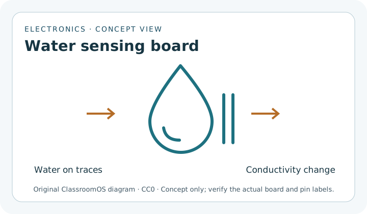
Pin Wiring+ to 5V- to GNDS to analog input
Water sensor module for detecting liquid level. Original ClassroomOS concept diagram · CC0 1.0; verify the actual component and pin labels.
Pin WiringVCC to 5VGND to GNDOUT/S to digital input
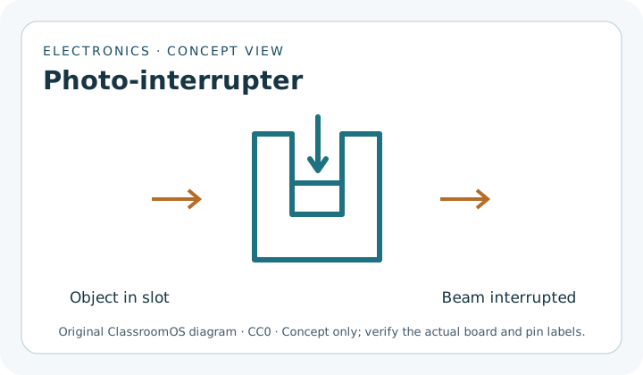
Photo-interrupter module for detecting when an object breaks a light beam. Original ClassroomOS concept diagram · CC0 1.0; verify the actual component and pin labels.
Pin WiringR to PWM digital pinG to PWM digital pinB to PWM digital pin- / GND to GND
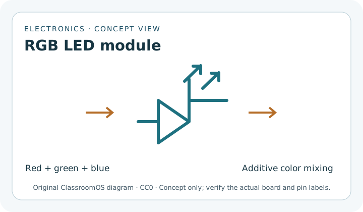
RGB LED module for mixing red, green, and blue light with PWM. Original ClassroomOS concept diagram · CC0 1.0; verify the actual component and pin labels.
Pin WiringR to PWM digital pinG to PWM digital pinB to PWM digital pin- / GND to GND
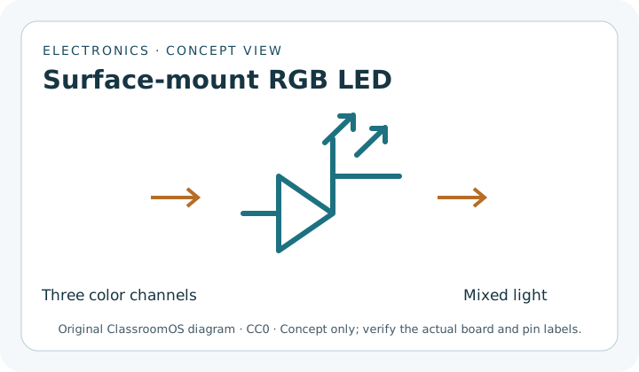
SMD RGB module for compact color mixing with PWM control. Original ClassroomOS concept diagram · CC0 1.0; verify the actual component and pin labels.
Pin WiringR to digital/PWM pinG to digital/PWM pin- / GND to GND
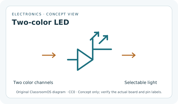
Two-color LED module for red, green, or mixed-color status output. Original ClassroomOS concept diagram · CC0 1.0; verify the actual component and pin labels.
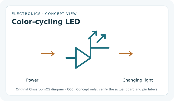
Pin WiringS to digital output+ to 5V- to GND
Seven-color flash LED module for simple automatic color effects. Original ClassroomOS concept diagram · CC0 1.0; verify the actual component and pin labels.
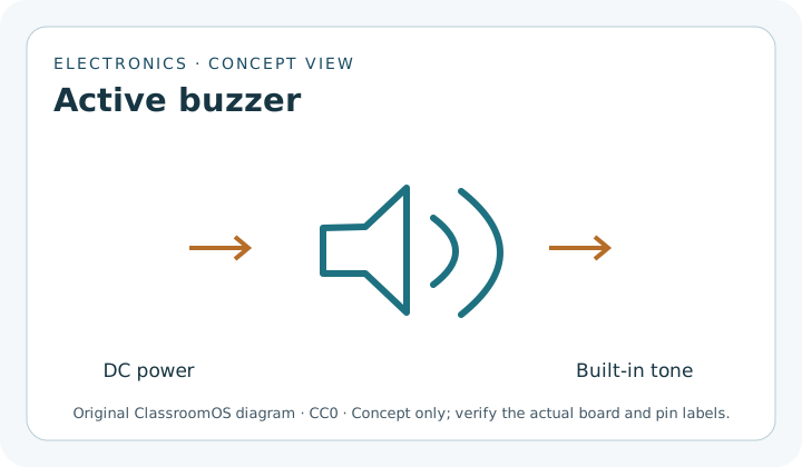
Pin WiringS to digital output+ to 5V- to GND
Active buzzer module for simple on/off sound output. Original ClassroomOS concept diagram · CC0 1.0; verify the actual component and pin labels.
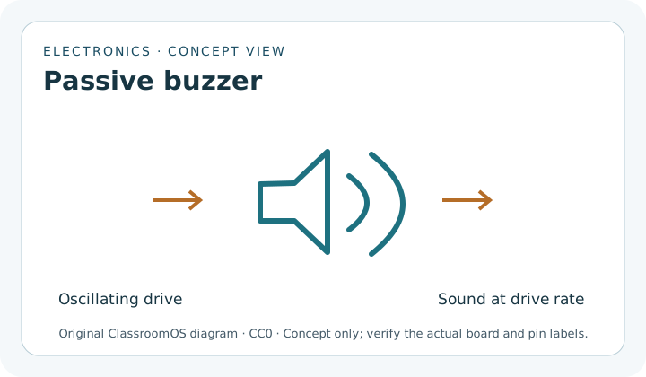
Pin WiringS to PWM/tone pin+ to 5V- to GND
Passive buzzer module for programmable tones and pitches. Original ClassroomOS concept diagram · CC0 1.0; verify the actual component and pin labels.
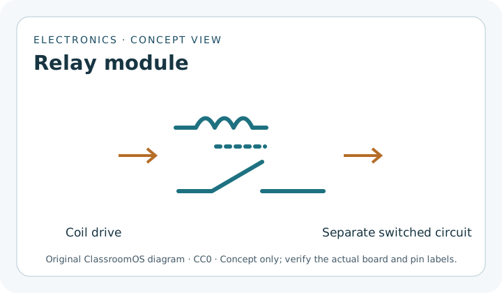
Pin WiringVCC to 5VGND to GNDIN/S to digital outputCOM/NO/NC to switched circuit
Relay module for switching a separate higher-power circuit. Original ClassroomOS concept diagram · CC0 1.0; verify the actual component and pin labels.
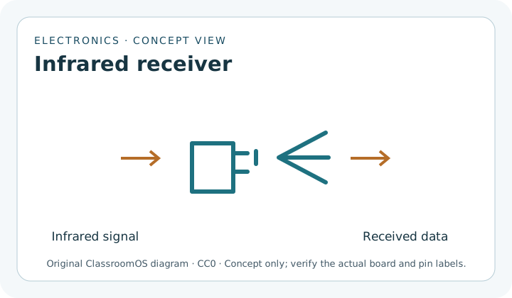
Pin WiringS/OUT to digital input+ to 5V- to GND
IR receiver module for reading signals from infrared remotes. Original ClassroomOS concept diagram · CC0 1.0; verify the actual component and pin labels.
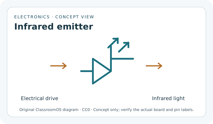
Pin WiringS/IN to digital output+ to 5V- to GND
IR emission module for sending infrared light signals. Original ClassroomOS concept diagram · CC0 1.0; verify the actual component and pin labels.
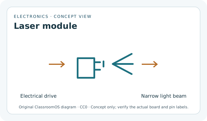
Pin WiringS/IN to digital output+ to 5V- to GND
Laser transmitter diode module for narrow-beam light output. Original ClassroomOS concept diagram · CC0 1.0; verify the actual component and pin labels.
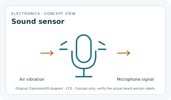
Pin WiringVCC to 5VGND to GNDAO to analog inputDO to digital input
Sound sensor modules for detecting noise level or sound events. Original ClassroomOS concept diagram · CC0 1.0; verify the actual component and pin labels.
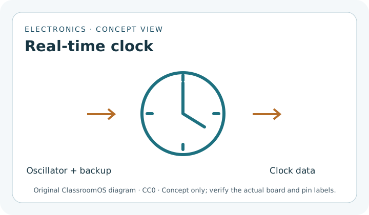
Pin WiringVCC to 5VGND to GNDSCL to I2C clockSDA to I2C data
DS1307 real-time clock module for keeping date and time. Original ClassroomOS concept diagram · CC0 1.0; verify the actual component and pin labels.
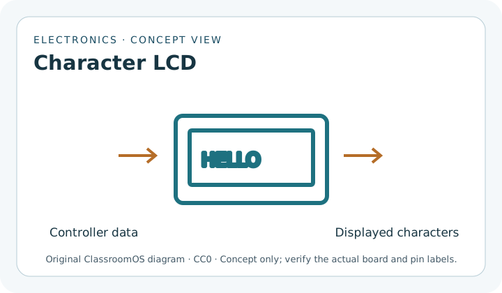
Pin WiringVCC to 5VGND to GNDSCL to I2C clockSDA to I2C data
LCD module for displaying sensor values and messages. Original ClassroomOS concept diagram · CC0 1.0; verify the actual component and pin labels.
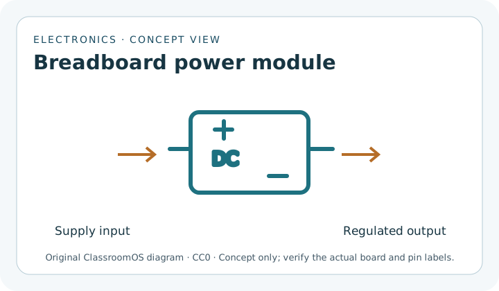
Pin WiringDC IN to 6.5V-9V supply5V to breadboard + rail3.3V to low-voltage railGND to breadboard - rail
Breadboard power supply module for feeding 5V or 3.3V rails. Original ClassroomOS concept diagram · CC0 1.0; verify the actual component and pin labels.
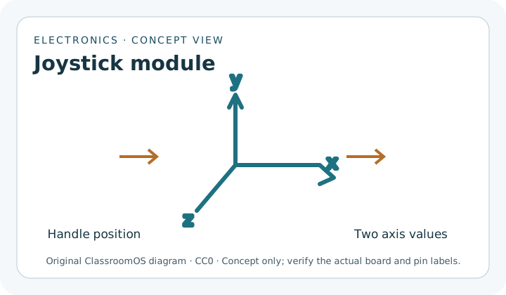
Pin WiringVCC to 5VGND to GNDVRx to analog inputVRy to analog inputSW to digital input
Joystick module for reading X/Y movement and push-button input. Original ClassroomOS concept diagram · CC0 1.0; verify the actual component and pin labels.
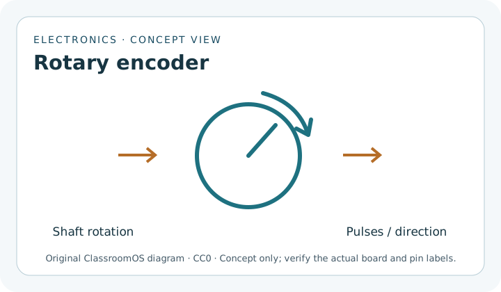
Pin Wiring+ to 5VGND to GNDCLK to digital inputDT to digital inputSW to digital input
Rotary encoder module for reading turns, direction, and button presses. Original ClassroomOS concept diagram · CC0 1.0; verify the actual component and pin labels.
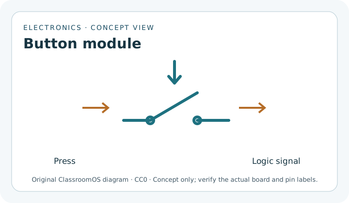
Pin WiringS to digital input+ to 5V- to GND
Button module for simple press and release input. Original ClassroomOS concept diagram · CC0 1.0; verify the actual component and pin labels.
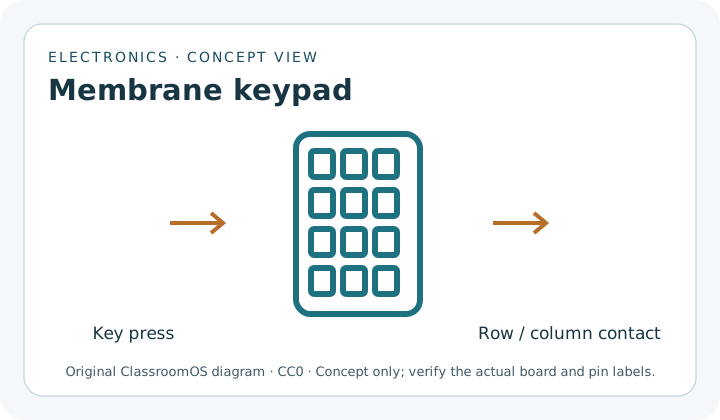
Pin WiringS to digital input+ to 5V- to GND
Membrane switch module for touch-style press input. Original ClassroomOS concept diagram · CC0 1.0; verify the actual component and pin labels.
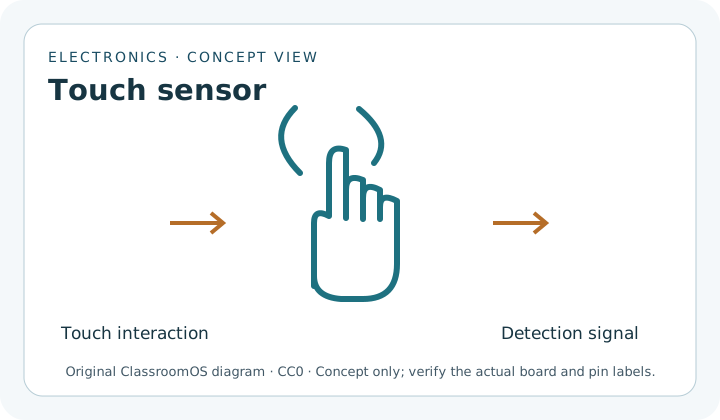
Pin WiringS to digital input+ to 5V- to GND
Metal touch module for detecting finger contact on a conductive pad. Original ClassroomOS concept diagram · CC0 1.0; verify the actual component and pin labels.
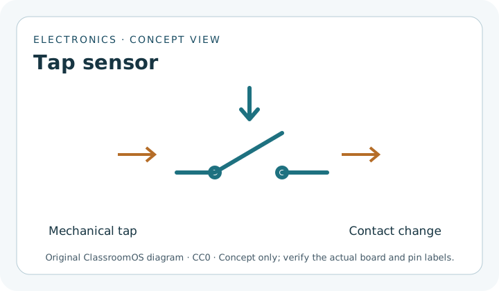
Pin WiringS to digital input+ to 5V- to GND
Tap module for detecting knocks, taps, or vibration events. Original ClassroomOS concept diagram · CC0 1.0; verify the actual component and pin labels.
Kit Overview
This style of sensor kit is popular because it gives beginners a large variety of modules at a relatively low cost. It works well as an introduction to physical computing because each board usually exposes a simple set of pins for power, ground, and signal.
Compatibility Note The kit is commonly used with Arduino-style boards and is also compatible with STM32 hardware in principle, but STM32 wiring and software support may require separate tutorials and examples.
Power Warning The Elegoo power supply module expects 6.5V to 9V DC through a 5.5 mm × 2.1 mm plug. Do not exceed that range, or you risk damaging the board and other chips connected to it.
What is included The kit provides sensor and interface modules only. You still need jumper wires and a controller board to actually use them.
Best use case Quick labs where students compare many sensing methods without soldering separate circuits from raw parts.
What to learn first Always identify whether a module is an input sensor, an output device, or an interface board before wiring it.
How To Think About Sensor Modules
Not every board in a sensor kit is actually a sensor. Some are inputs that measure the world, some are outputs that create light or sound, and some are support modules that handle display, power, or communication.
Type
What It Does
Examples From This Kit
Environmental / Physical Input
Measures light, motion, sound, temperature, humidity, water, or magnetic effects
Photo-resistor, PIR, flame, hall, sound, DS18B20, DHT-style temperature-humidity, water level
Helps the system keep time, communicate, or power other modules
RTC module, IR receiver/emitter, LCD1602, power supply, GY-521 motion board
Component Listing, Organized By Function
The original kit inventory is much easier to use once it is grouped into categories.
6 Modules
User Controls
Joystick Module
Rotary Encoder Module
Button Module
Membrane Switch Module
Metal Touch Module
Tap Module
14 Modules
Environmental and Motion Sensors
Ultrasonic Sensor Module
HC-SR501 PIR Sensor Module
Flame Sensor Module
Linear Hall Module
Digital Temperature Module
18B20 Temp Module
Temperature and Humidity Module
Photo-resistor Module
GY-521 Module
Avoidance Module
Tracking Module
Magnetic Spring Module
Water Level Sensor
Photo-interrupter Module
6 Modules
Sound, Light, and Alert Outputs
RGB LED Module
SMD RGB Module
Two-tone Color Module
7 Color Flash Module
Active Buzzer Module
Passive Buzzer Module
7 Modules
Detection, IR, and Switching
Relay Module
IR Receiver Module
IR Emission Module
Laser Emit Module
Shake Module
Tilt Switch Module
Big Sound Module and Small Sound Module
3 Modules
Time, Display, and Power
DS-1307 RTC Module
LCD1602 Module with pin header
Power Supply Module
Most Useful Beginner Modules To Start With
If you only want a few strong first experiments, these modules give the best learning payoff with minimal setup.
Module
Why It Is Useful
Good First Project
Photo-resistor Module
Easy way to learn analog input and voltage division
Automatic night light
Ultrasonic Sensor Module
Teaches timing, distance measurement, and object detection
Parking sensor or distance alarm
HC-SR501 PIR Sensor
Simple motion sensing with very visible real-world uses
Motion-triggered lamp or buzzer
Temperature and Humidity Module
Introduces environmental monitoring and data logging
Mini weather station
Joystick Module
Fast path into two-axis analog control plus a pushbutton
Menu navigation or game controller input
LCD1602 Module
Makes sensor data visible without a computer screen
Display distance, temperature, or menu states
Starter Project Ideas
These pairings help students see how different modules can work together. Combining two sensors that measure the same thing is called sensor fusion: the GY-521's gyro and accelerometer are the classic pair. See Sensor Fusion.
Motion Alarm Use the PIR sensor with an active buzzer and RGB LED to create a simple room monitor.
Light Meter Use the photo-resistor and LCD1602 to display changing light values in real time.
Digital Thermometer Pair the DS18B20 or temperature module with the LCD display for a live readout.
Distance Warning System Combine the ultrasonic module with LEDs or a passive buzzer that changes pitch as an object gets closer.
Door Open Detector Use the magnetic spring module to sense when a magnet moves away from the frame.
Remote-Control Demo Use the IR receiver and emitter modules to explore line-of-sight communication.
From Physical Change to Digital Data
A sensor is a measurement chain. A transducer responds to a physical quantity, conditioning circuitry turns that response into a usable electrical signal, and the controller converts the signal into data. Your code then calibrates, filters, and interprets that data. A module's output is not automatically the same thing as the real-world quantity.
Signal Type
What the Controller Receives
What to Check
Digital state
HIGH or LOW
Logic voltage, active-high/active-low behavior, pull-up or pull-down
Analog voltage
A range sampled by an ADC
Maximum input voltage, ADC reference, resolution, source impedance
Voltage compatibility comes before code. A 5 V module output can exceed a 3.3 V controller input rating even when both boards power up correctly. Check supply voltage, logic-high thresholds, and absolute maximum input voltage in both datasheets. Use a divider or proper level shifter when required.
Resolution, Accuracy, Precision, and Range
RangeThe lowest to highest quantity the sensor can measure without saturating or leaving its specified behavior.
ResolutionThe smallest change the complete system can represent. A 10-bit ADC provides 1,024 codes, but noise may hide the smallest steps.
AccuracyHow close a reading is to the true value after considering offset, gain error, environment, and calibration.
PrecisionHow closely repeated readings agree. A sensor can be precise but consistently wrong.
Response timeHow quickly the reading follows a real change. Fast sampling cannot make a physically slow sensor respond faster.
Drift and hysteresisReadings may change with time or depend on whether the measured value approached from above or below.
Calibration and Filtering Workflow
Read the datasheet: identify pins, operating voltage, output type, range, accuracy, timing, and environmental limits.
Establish references: collect readings at two or more known conditions, including the part of the range your project will actually use.
Graph raw data: keep raw readings and units. Look for offset, nonlinearity, saturation, outliers, and warm-up behavior.
Fit a conversion: turn ADC codes or timing into meaningful units. Do not claim more decimal places than the sensor accuracy supports.
Filter deliberately: a moving average reduces random noise but adds delay. A median filter rejects occasional spikes. Filtering cannot repair poor wiring or an overloaded sensor.
Validate separately: test at conditions not used to create the calibration, then report error and uncertainty.
Sensor Lab: Build an Evidence-Based System
Choose one module and produce a measurement system another student can verify. The engineering work is the evidence, not merely a serial monitor that prints changing numbers.
Stage
Required Evidence
Plan
Measured quantity, usable range, pinout, voltage levels, signal type, and safety constraints
Wire
Labeled schematic or connection table with a shared reference ground where required
Acquire
Timestamped raw readings at a stated sample rate, including a timeout or missing-data behavior
Calibrate
Known references, conversion method, units, and limits of the calibration
Test
Repeated trials, a graph, and an error or variability calculation
Respond
An LED, buzzer, display, motor, or logged event driven by a justified threshold or control rule
Reflect
One false reading or failure mode and a specific hardware or software improvement
Ultrasonic distanceCompare measurements against a ruler at several distances. Investigate angle, soft surfaces, minimum range, and timeout behavior.
Light sensingRecord raw analog values under controlled light levels. Test shielding, sensor angle, threshold hysteresis, and averaging.
Temperature loggingCompare against a reference thermometer after settling. Separate resolution, repeatability, response time, and absolute error.
Motion or vibrationMeasure idle noise first, then define an event threshold that rejects false triggers. Report both missed events and false positives.
Threshold hysteresis: use different turn-on and turn-off values when readings hover near a boundary. For example, turn a fan on above 28 °C and off below 26 °C. This prevents rapid chatter.
Common Beginner Mistakes
Forgetting the controller board This kit does not run by itself. Every module needs a microcontroller and jumper wires.
Mixing analog and digital expectations Some modules output a changing analog value, while others simply report HIGH or LOW.
Overpowering the supply board Stay within the specified 6.5V to 9V DC range for the dedicated power module.
Assuming every board is a sensor Relay, LCD, and buzzers are useful modules, but they are outputs or interface boards rather than sensors.
Skipping pin labels Check each module for power, ground, digital, analog, or special communication pins before wiring.
Expecting STM32 instructions in-kit The kit may physically work with STM32 boards, but classroom examples are often written for Arduino first.
Quick Check
1. What extra hardware do you need to actually use this sensor modules kit?
2. Which module is best known for distance measurement?
3. What is the safe input voltage range for the Elegoo power supply module listed in this lesson?