Engineering · Arduino · Hardware Anatomy
Inside Your Board
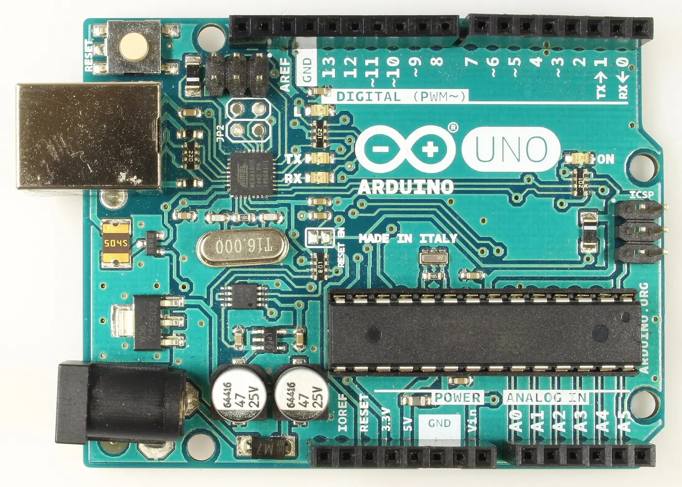
Arduino boards share a programming language, but not the same anatomy. Start with the UNO R3: find power, read an input, and control an output. Then compare boards and explain which features your project needs.
← Back to EngineeringBoard anatomy simulator
Trace the board's brain
First investigation: select GND, A0, and ~D9 below. Which provides a reference, which measures a voltage, and which can produce pulses? The inspector explains each choice.
A is more than a collection of parts. Copper paths carry power and signals between connectors and one or more computing “brains.” Choose a board, then select any white target or exposed pin. The yellow route shows where information or power travels.
Exposed pins
Select an individual label. A tilde such as means that pin has an extra ability; it is still a normal digital pin too.
Learn the board language, one job at a time
Start with , , and . Then follow related concepts. You can understand a board without memorizing every chip name.
Concepts opened are tracked for this session only.
Build from the exact manufacturer's diagram, not this conceptual map: UNO R3 · Nano Every · UNO R4 WiFi · UNO Q.
Use the labels
What should this wire connect to?
Practice on a UNO R3. A pin number is an address for your code, not a voltage. D9 means digital pin 9; A0 means analog input 0. One physical pin can have several jobs, but your circuit must choose compatible uses.
Supply energy and provide the common reference. VIN is an input before regulation, not a digital pin.
D reads or writes HIGH/LOW. A measures voltage. ~ adds PWM output: fast HIGH/LOW pulses, not a smooth analog voltage.
These carry messages. On the UNO R3, A4/SDA and A5/SCL are shared functions, not extra independent pins.
Plan before wiring: name the signal, select a pin, check the component’s supply and logic voltages, and include the return path. A GPIO sends a control signal; a motor needs a driver and a suitable power source.
Continue with breadboard connections and Arduino programming foundations.
Same language, different hardware
From one brain to two
Every board in the menu above runs the same setup() / loop() sketch structure and the same core functions — pinMode(), digitalWrite(), analogRead(). What actually differs board to board is the hardware you're programming: the number of usable pins, how much sketch memory you get, whether the chip talks to Wi-Fi or Bluetooth on its own, and whether its pins run at 5 volts or 3.3 volts. The sketch structure is familiar, but pin mappings, libraries, USB behavior, and timing may require code changes. On UNO Q, Arduino sketches run on the MCU; Linux applications run separately on the MPU.
The lineup
Eight boards, side by side
These boards span classic classroom controllers, connected devices, and Linux-powered edge computing. Scan the table, then use the picker below to match a project to a board.
| Board | Chip | Digital / Analog pins | Flash memory | Logic voltage | Best for |
|---|---|---|---|---|---|
| Uno R3 | ATmega328P | 14 / 6 | 32 KB | 5V | The default choice — most tutorials, kits, and shields target this board first. |
| Nano | ATmega328P | 14 / 8 | 32 KB | 5V | Same brain as the Uno in a breadboard-friendly size — great for permanent builds. |
| Mega 2560 | ATmega2560 | 54 / 16 | 256 KB | 5V | Big projects: many sensors and motors at once, or four hardware serial ports. |
| Leonardo / Micro | ATmega32u4 | Leonardo: 20 / 12; Micro: 20 / 12 | 32 KB | 5V | Native USB HID; Leonardo and Micro pin counts differ—check the exact model. |
| UNO R4 WiFi | RA4M1 + ESP32-S3 | 14 / 6 | 256 KB (main MCU) | 5V GPIO Wi-Fi + BT | Modern UNO projects needing wireless, a 12 × 8 LED matrix, DAC, CAN, or native USB. |
| UNO Q | QRB2210 MPU + STM32U585 MCU | UNO-style headers | Linux storage + 2 MB MCU flash | 3.3V MCU GPIO Wi-Fi + BT | Camera, AI, or Linux applications paired with precise real-time physical control. |
| ESP32 | Varies by ESP32 model | Board-dependent GPIO / ADC | Module-dependent | 3.3V Wi-Fi + BT | Internet of Things projects, networked sensors; check the exact module’s GPIO and memory. |
| ESP8266 (NodeMCU / D1 Mini) | Single-core Xtensa | Board-dependent GPIO / 1 ADC | 4 MB | 3.3V Wi-Fi | Budget Wi-Fi projects where you don't need Bluetooth or many pins. |
Interactive picker
Match your project to a board
Check every requirement your project actually has. The recommendation updates live — and explains its reasoning, the way a good engineer should.
Arduino Uno
- No special requirements checked yet — the Uno is the safest, best-documented starting point.
The gotcha
5 volts vs. 3.3 volts
The Uno, Nano, Mega, and Leonardo all read and write pins at 5V. The ESP32 and ESP8266 read and write pins at 3.3V — and their pins are not tolerant of 5V. Check the exact board and sensor specifications before joining their signals.
5V family
UNO R3 · classic Nano · Nano Every · Mega · Leonardo/Micro · UNO R4 GPIO. A driven HIGH output is near the board’s logic supply; input thresholds are specified separately. Most beginner sensor modules and shields are designed around this voltage.
3.3V family
ESP32 · ESP8266 · UNO Q MCU GPIO. Not every board named Nano uses 5V logic. A driven HIGH output is near 3.3V; input thresholds are specified separately. Feeding a 5V sensor's output straight into one of these pins can damage the chip.
Quick check
Test your board sense
1. A project needs 30 digital pins for an LED matrix. Which board fits?
2. Which board can act as a USB keyboard on its own?
3. Which board runs its pins at 3.3V instead of 5V?
4. What's the risk of wiring a 5V sensor's output straight into an ESP32 pin?
5. What structure is shared by Arduino sketches on these controllers?
Enclosure & Mounting
3D Print a Custom Arduino Case
Housing your board protects against accidental shorts on a metal bench or workbench debris. Open Forge to generate a custom enclosure with standoffs aligned to the UNO R3 / R4 mounting holes, cable port cutouts, and ventilated lids with custom engraving.